A loose terminal screw, damaged gland, poorly prepared conductor or moisture path can turn a reliable limit signal into an intermittent fault, overheating connection or unsafe loss of control. You will be able to separate a terminal-chamber problem from a failed switch, cable or control input, then troubleshoot it without compromising flame-proof protection.
Key takeaways
- Check for heat discolouration before replacing the limit switch.
- Test the cable, terminal and switch separately to locate the fault.
- Inspect loose screws, vibration damage, moisture and damaged cable glands.
- Use certified parts and retain installation records for hazardous-area repairs.
How loose connections, vibration and moisture destroy a terminal
A loose FLP limit switch terminal fails through heat before it fails electrically. Poor contact increases resistance, causing voltage drop and localised heating that discolours the terminal, carbonises insulation and eventually opens the circuit.
Vibration from conveyors, hoists, dampers and rotating machinery progressively backs out a screw when the terminal is not vibration-resistant or the conductor is poorly prepared. A conductor that is too small, has damaged strands, lacks a suitable ferrule where specified, or sits partly outside the clamp creates the same high-resistance joint.
Over-tightening is also destructive: it deforms the terminal, cuts strands and weakens the connection.
The installation faults most likely to start the failure are:
- Cable movement pulling against the terminal instead of being restrained at the gland.
- Thermal cycling that repeatedly expands and contracts the conductor and screw.
- An incorrectly selected or loose cable gland, damaged sealing washer, cracked stopping plug or improvised bolt in an unused entry.
- Water or condensation entering the chamber, followed by corrosion and tracking from coastal salt contamination.
- A damaged enclosure joint or cover flamepath that has been scratched, contaminated or assembled incorrectly.
- Actuator overtravel, side loading, a bent lever or a loose mounting that transfers impact into the switch body.
A weatherproof gland is not automatically suitable for an Ex d assembly. The gland, plug, cable diameter, conductor arrangement and enclosure must match the equipment certificate and hazardous-area protection concept.
Recurring FLP limit switch terminal failure in Chennai deserves a history check for monsoon ingress, washdown, cable movement and nearby vibration before you replace the switch.
How to identify the failed part before replacing the switch
Do not condemn the switch until the signal has been tested at both sides of the terminal chamber. A correct mechanical trip with an unstable electrical result points to wiring, termination or contacts—not automatically to the complete FLP assembly.
1. Make the circuit and hazardous area safe under the site permit, then record the Ex d marking, certificate number and wiring drawing. Do not open the enclosure in a potentially explosive atmosphere or replace certified internal parts with similar-looking components.
2. Inspect the gland, cable sheath, terminal screw, crimp lug, internal link and flexible lead. Look for water, corrosion, heating, discoloration, loose strands and crushed insulation. A damaged gland or field junction box can imitate a switch failure.
3. With the circuit isolated and proven dead, check continuity at the switch terminals while operating the actuator. Flex the cable and gland without forcing them. A changing reading identifies a termination, cable, gland or junction fault; a contact that remains open or closed through full actuator travel indicates a failed contact mechanism or misalignment.
4. Compare the switch-side result with the control-panel input. Stable continuity at the switch but no panel change places the fault in the field cable, junction or input circuit. A panel input that remains wrong after the field pair is verified points to the input module.
For flp limit switch terminal problems in chennai, check monsoon water entry, washdown, coastal corrosion and cable movement. A recurring flame proof limit switch fault in chennai can also come from actuator overtravel, side loading or vibration rather than the terminal block.
A safe test sequence for an industrial FLP limit switch
An intermittent signal is not proof that the limit switch itself has failed. For industrial FLP switch troubleshooting in Chennai, test the complete certified assembly in this order.
1. Stop the equipment, isolate every electrical supply, apply lockout/tagout and obtain the site permit. Record the switch nameplate, Ex d marking, certificate number, circuit voltage and contact rating.
2. Confirm the hazardous area is cleared by the site gas-testing procedure before opening anything. Prove the circuit dead with an approved tester, test the tester on a known live source, then retest. Do not open an Ex d enclosure in a potentially explosive atmosphere.
3. With power isolated, inspect the cable gland, stopping plugs, enclosure condition and cable sheath. A weatherproof gland is not automatically suitable for Ex d service.
4. Check conductor preparation, terminal seating and manufacturer-specified torque. Look for loose strands, crushed insulation, corrosion, moisture, heat discolouration and arcing marks. Do not scratch or machine the flamepath.
5. Disconnect sensitive panel electronics as the circuit drawing requires, then test conductor-to-conductor and conductor-to-earth insulation resistance with the specified test voltage. Measure continuity and contact resistance in each switch position.
6. Operate the actuator slowly while monitoring continuity and mechanical travel. If continuity is stable, restore the circuit under controlled conditions and measure voltage across the contact while the real load operates; a low-current meter test can miss a contact that fails under load.
If the fault follows the field cable or panel input, do not condemn the switch. Stop if the certificate, gland arrangement or flamepath is uncertain, and obtain the maker’s instructions before disturbing internal parts.
What to inspect inside the terminal chamber and cable entry
Open the chamber only after isolation, lockout/tagout, proving dead and confirming the hazardous-area permit allows it. Record the Ex d marking, certificate number and terminal layout before disturbing anything. Never scrape, file or paint the flamepath; a damaged joint can invalidate the enclosure.
Check the chamber in this order:
- Verify each terminal number, link and screw against the maker’s drawing. Look for looseness, heat browning, carbon, corrosion and strands outside the clamp.
- Check conductor size, stripped length, ferrules or lugs and insulation clearance. Re-terminate only with the specified parts and torque; over-tightening can cut strands.
- Inspect the gland, sealing washer, locknut and unused entries for the correct certified type, tightness, cracks and water tracks. A damaged plug or gland can admit Chennai monsoon water and salt.
- Confirm the protective earth is continuous, secured to the marked earth point and free of corrosion. Do not use the flameproof joint as an earth path.
- Examine the cover and base joint for dents, dirt, corrosion or trapped gasket material. Clean only as the certificate or instructions permit.
- Check actuator, roller and mounting alignment by hand. A misaligned cam can hold contacts open or closed while the terminals remain sound.
A limit switch terminal chamber issue in Chennai becomes clearer when you separate these findings:
| Finding | Likely source | Confirm without harming Ex d integrity |
|---|---|---|
| Loose terminal or heat mark | Termination fault | Isolated continuity and torque check |
| Good terminals, signal changes while flexing cable | Gland or conductor fault | Insulation and continuity test |
| Correct circuit, actuator fails to change state | Mechanism or alignment | Observe contact operation |
| Moisture or tracking | Entry, condensation or corrosion | Inspect seals and enclosure history |
When the correct repair requires certified parts and installation records
Stop field repair when the proposed replacement or modification cannot be matched to the switch’s certified design. A terminal block that looks identical can have different creepage, clearance, temperature rating or clamping construction, and fitting it can invalidate the Ex d protection.
1. Do not proceed without the maker’s certificate and assembly drawing when the terminal block, contact unit, cover, flamepath, gland plate or stopping plug is damaged or being replaced.
2. Obtain the maker’s installation instructions when terminal torque, conductor size, stripping length, gasket, grease, enclosure-joint treatment or cable-entry arrangement is unclear. Do not guess from a similar switch.
3. Stop if the enclosure has machining marks, corrosion, impact damage, cross-threading or a damaged flamepath. A replacement cover or filing operation requires approved parts and specialist assessment.
4. Escalate when the certificate marking does not match the hazardous-area classification, gas group or temperature class, or when an ordinary weatherproof gland has been installed. Replace it only with a gland and stopping plug certified for the enclosure, cable construction and diameter.
5. Seek specialist support after repeated failures, unexplained heating, arcing marks, water entry or mechanical overtravel. Recurrence after a terminal retightening indicates a design, alignment, cable-entry or environmental fault, not a completed repair.
If the unit is opened in a potentially explosive atmosphere, restore it only after isolation, permit and gas-clearance requirements are met. Record the certificate number, drawing revision, parts fitted, terminal torque, gland details, test results and enclosure-closure inspection. Shine Agencies can help match a replacement against those records rather than its appearance.
Related product
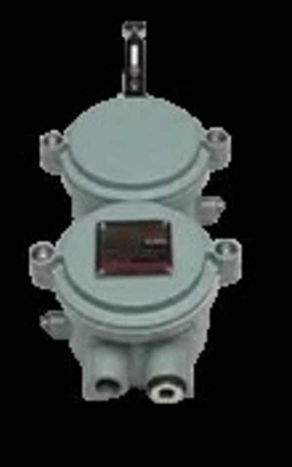
 | Flame Proof industrial Lighting FLP LIMIT SWIITCH WITH TERMINAL CHAMBER P RODUCT NAME : CAT NO : LS / 2C / 2021 ENCLOSURE : FLAME PROOF (Ex –d ), Gas G r o u p I I A , I I B , I I C As per IS/IEC 60079-1 : 2014 PROTECTION... View product → |
Frequently asked questions
Why do FLP limit switch terminals fail?
Loose connections increase resistance, creating localised heat that discolours terminals, damages insulation and opens the circuit. Vibration and moisture accelerate the damage.
How can you identify the failed part before replacing an FLP limit switch?
Isolate power, then test the cable, terminal connections and switch contacts separately. Look for heat damage, loose conductors, corrosion and continuity changes during actuator movement.
What should you inspect inside an FLP limit switch terminal chamber?
Inspect terminal screws, conductor strands, insulation, earthing connections, sealing surfaces and cable-gland entry for looseness, carbonisation, corrosion or moisture.
When does an FLP limit switch repair require certified parts and installation records?
Use certified replacement parts and qualified hazardous-area installation when the enclosure, flame path, cable entry or protection certification is affected. Record the parts, work performed and test results.
Keywords